Problem Statement
Ham radios typically require a power supply of 13,8V at a relatively high current. Here are some examples, based on the respective user’s manual recommendations:
| TRX model | TX power | Minimal PSU current rating |
|---|---|---|
| Xiegu G90 | 20W | 8A |
| Icom IC-2730A | 50W | 13A |
| Yaesu FT-857D | 100W | 22A |
An obvious way to power a radio would be to purchase a purpose-built, ham radio PSU. The thing is, these are pricey. At the time of writing, an Alinco DM-30E would run me upwards of 590 PLN. I don’t want to spend that kind of money when there’s a 10x cheaper alternative, and that’s used server PSUs. You can get them for cheap, at anywhere between 300W and 1000W of power. These come from decommisioned datacenter hardware, hence are rugged and widely available. It’s also a tried and tested solution in ham radio circles.
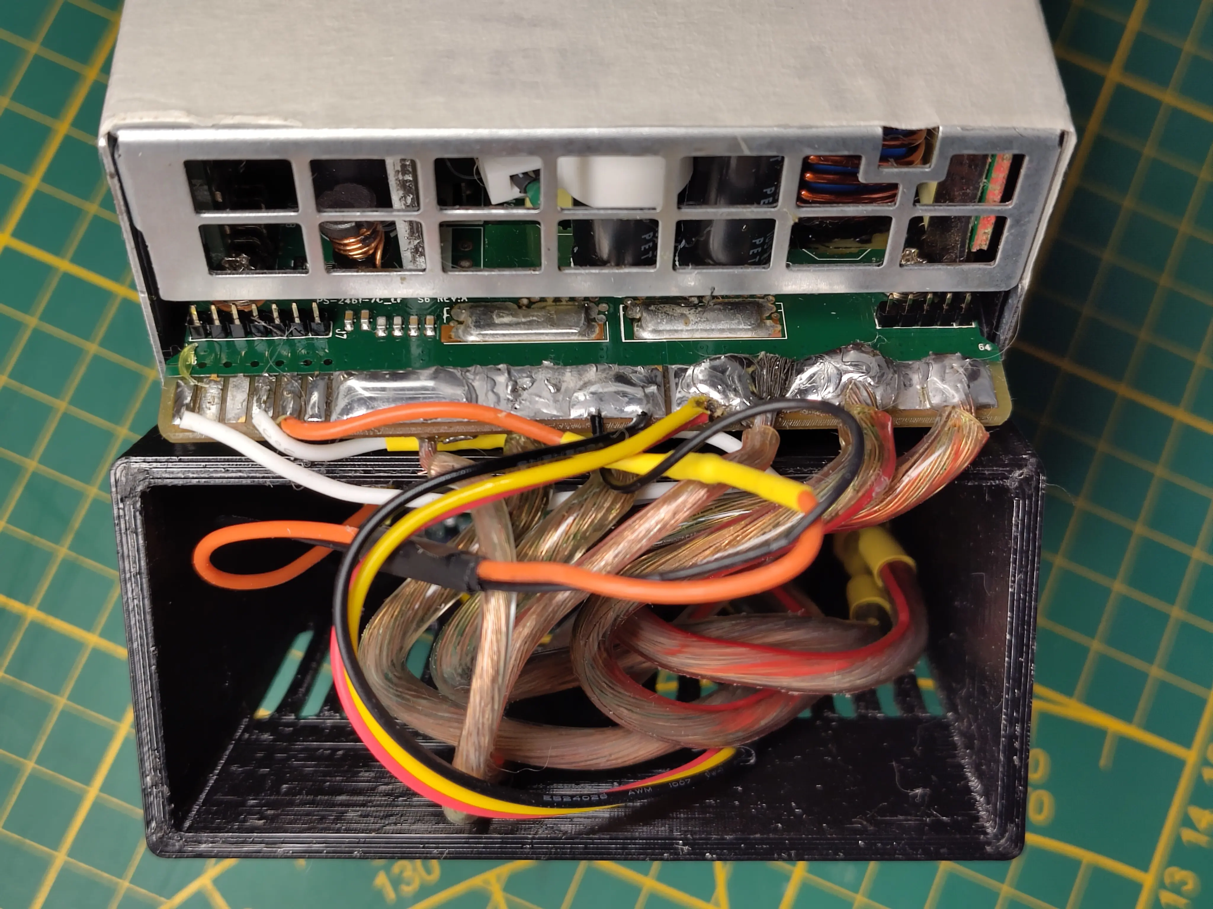
After initial research, I found the HP Enterprise product line PSUs to be the most approachable, given their hackability and availability in my area. They’re standardized in terms of the physical footprint and electrical interface (HPE Common Slot), even across multiple hardware generations.
Proof of Concept
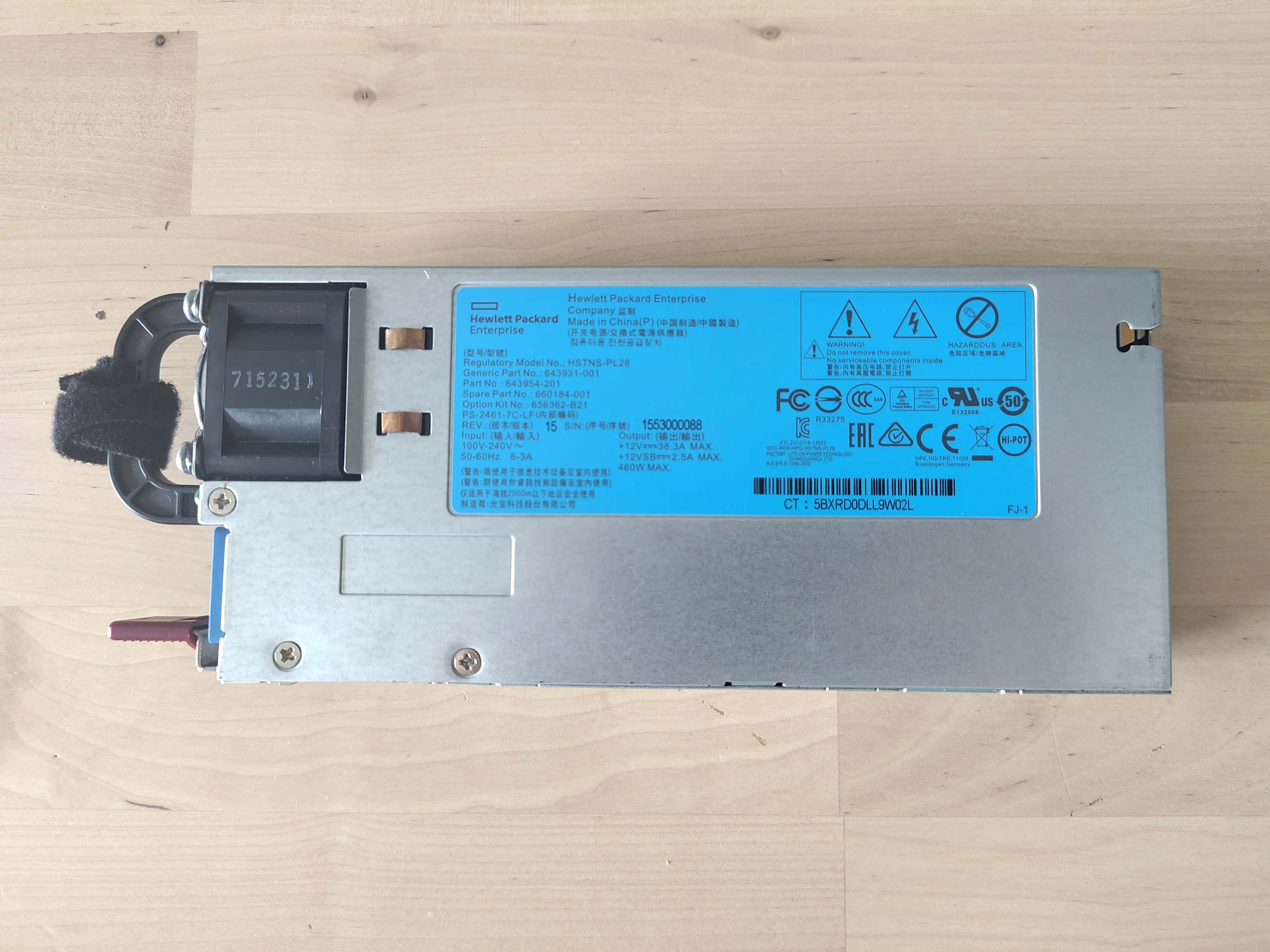
I got a HSTNS-PL28 460W unit for just 45 PLN. Per the specification, it can output up to 38.3A, at 12V. That’s plenty enough, even for a 100W radio (see table above).
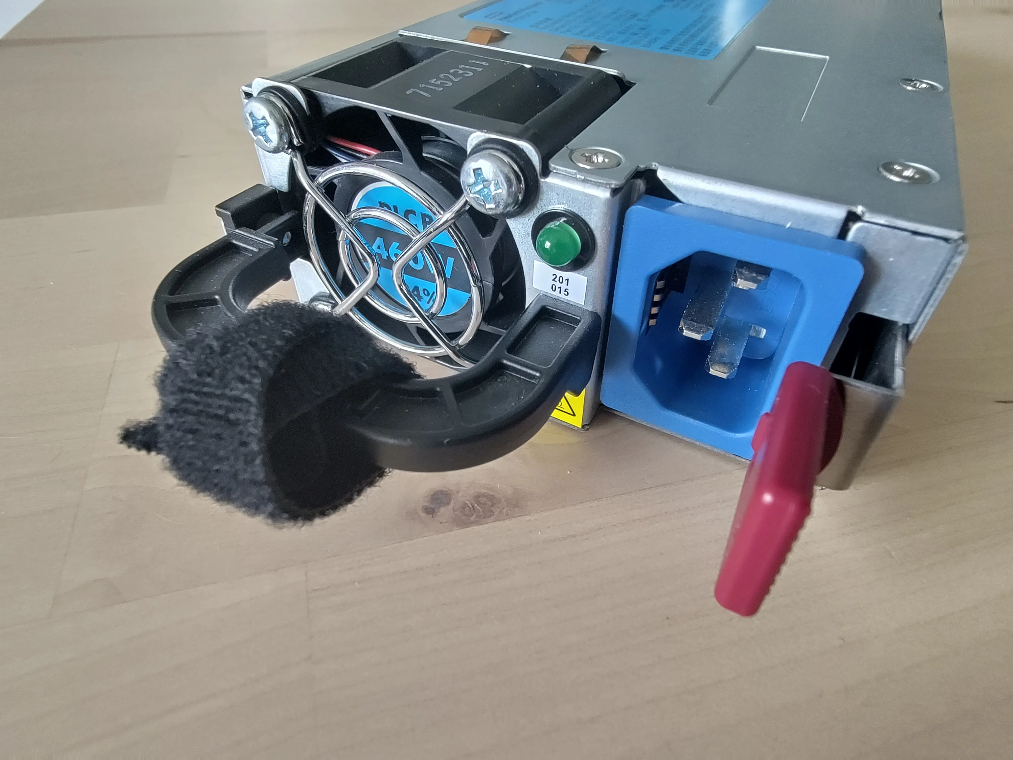
The first step was to figure out how to power on the main 12V rail. In a bare-bones shape, when connected to 230V AC, the unit would power on only in the standby sense — fan spin, power LED blinking.
I found this HPE Common Slot PSU specification over at the RCGroups forum:
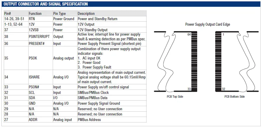
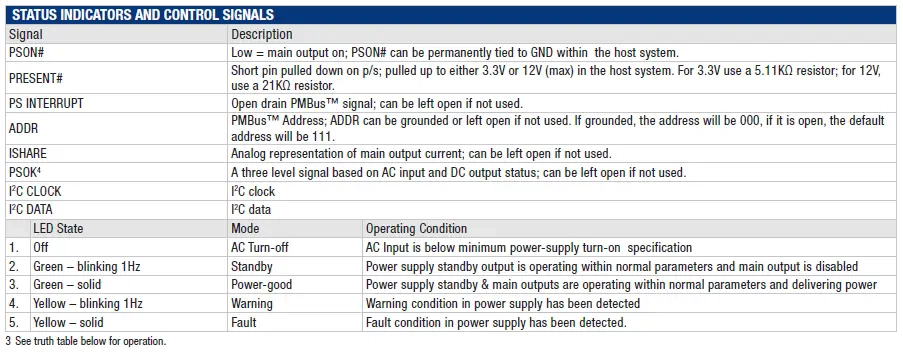
Per the above, pin 33 (PSON#) expects a PSU on/off control signal. I found mixed info on this topic, with the general consensus being that it needs to be pulled high. I tried with a 1kΩ resistor first, across pins 33 and 37 (12VSB). That wasn’t enough to achieve power on, so I’ve tried with a 330Ω instead, which worked just fine.
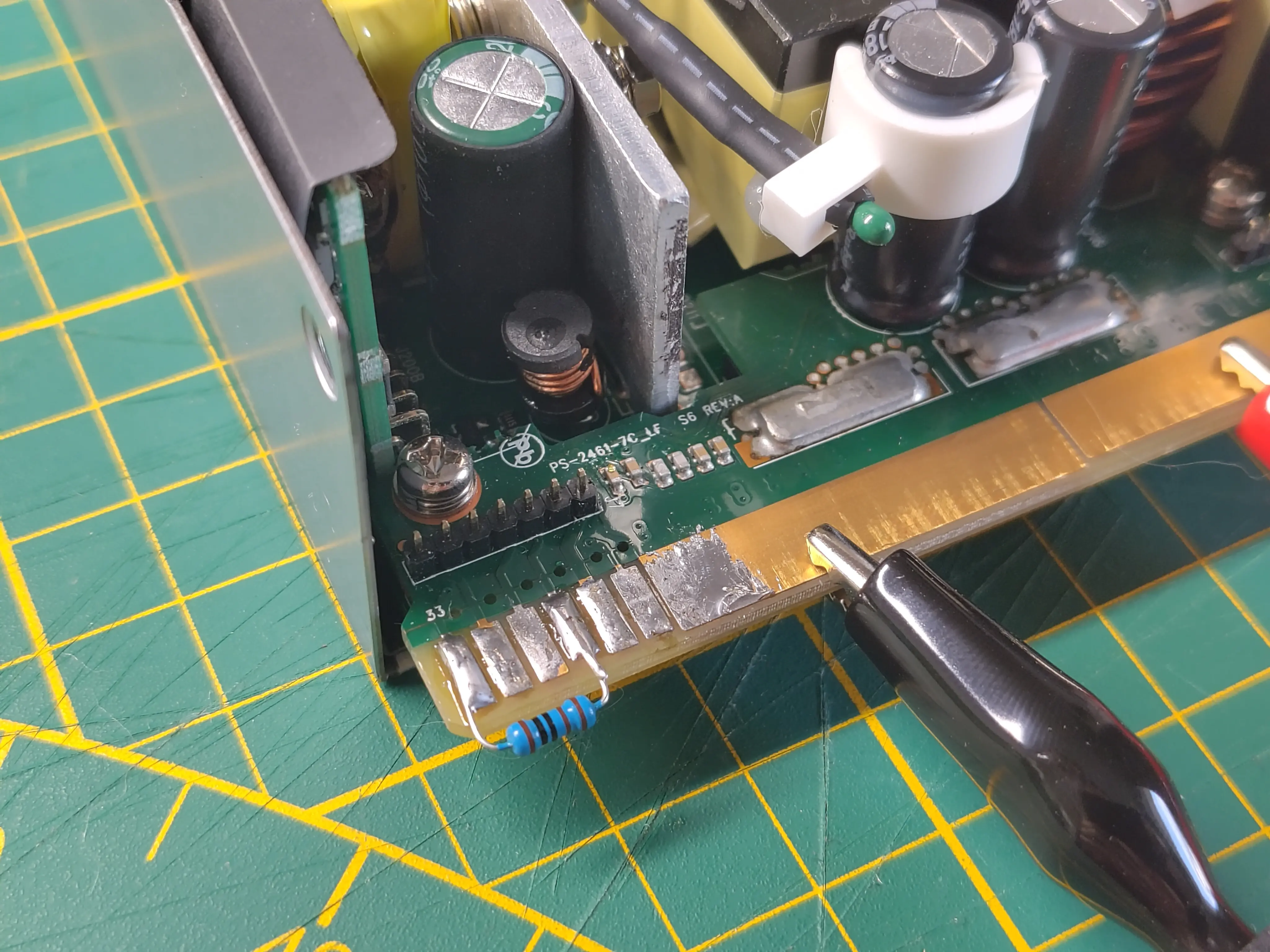
I’ve let the PSU run unloaded for ~10min, throughout which the 12V rail exhibited a stable voltage of ~12.3V. I didn’t perform a high-current (>10A) stress test, since I didn’t have an appropriate load at my lab. Nevertheless, this proves the concept. Should the PSU fail at high currents, it will be a specific unit’s problem, not a problem with the idea per se. Overall, the concept was now proven and I started designing the final device.
Design
Requirements
Here’s what I expect from the finished device:
- Power switch (standby/fully on).
- Standby power indicator (on the front).
- 2x XT60 receptable, each capable of 10A – sustained current.
- 2x banana receptable pair (positive, negative), each pair capable of 5A sustained current.
- Digital voltmeter with a ±0.1V precision and accuracy.
- All of the above I/O interfaces shall be exposed on a single front panel.
Electrical
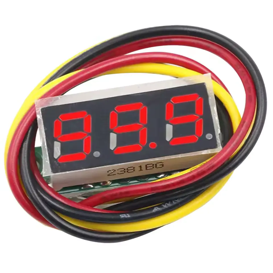
For the voltmeter, I found these little modules, for ~3PLN a piece. They’re reasonably sized and are quite flexible electrically. With a wide range of operation, allowing anywhere between 2,5V and 30V, they’re suitable for just about any hobby electronics project.
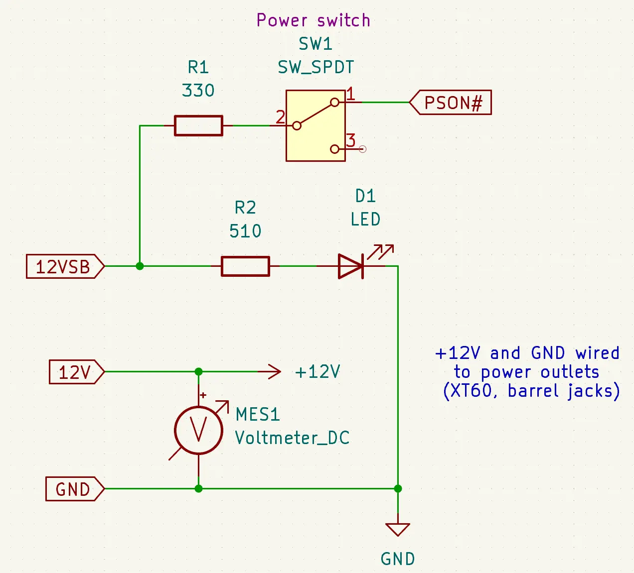
For the standby power indicator, I went with a yellow, 5mm LED. The mode of operation is simple:
- The LED is connected to
12VSBvia an appropriate voltage dropping resistor. - The LED lights up whenever
12VSBis high. This means it will stay on even when the PSU is fully powered up, but that’s fine by me. It’s simple and it gets the job done.
For the power switch, I chose a simple, black, rocker switch (ON-OFF). It doesn’t stick out much from the enclosure, while still clearly communicating the current state (unlike a push switch/button).
Regarding the XT60 and banana connectors, I just used whatever I already had lying around. All of these are generic, bulk-purchased AliExpress parts.
Here’s the complete schematic:
Mechanical
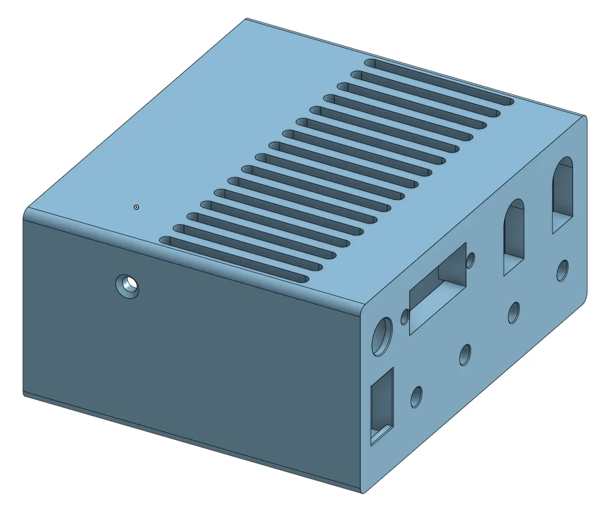
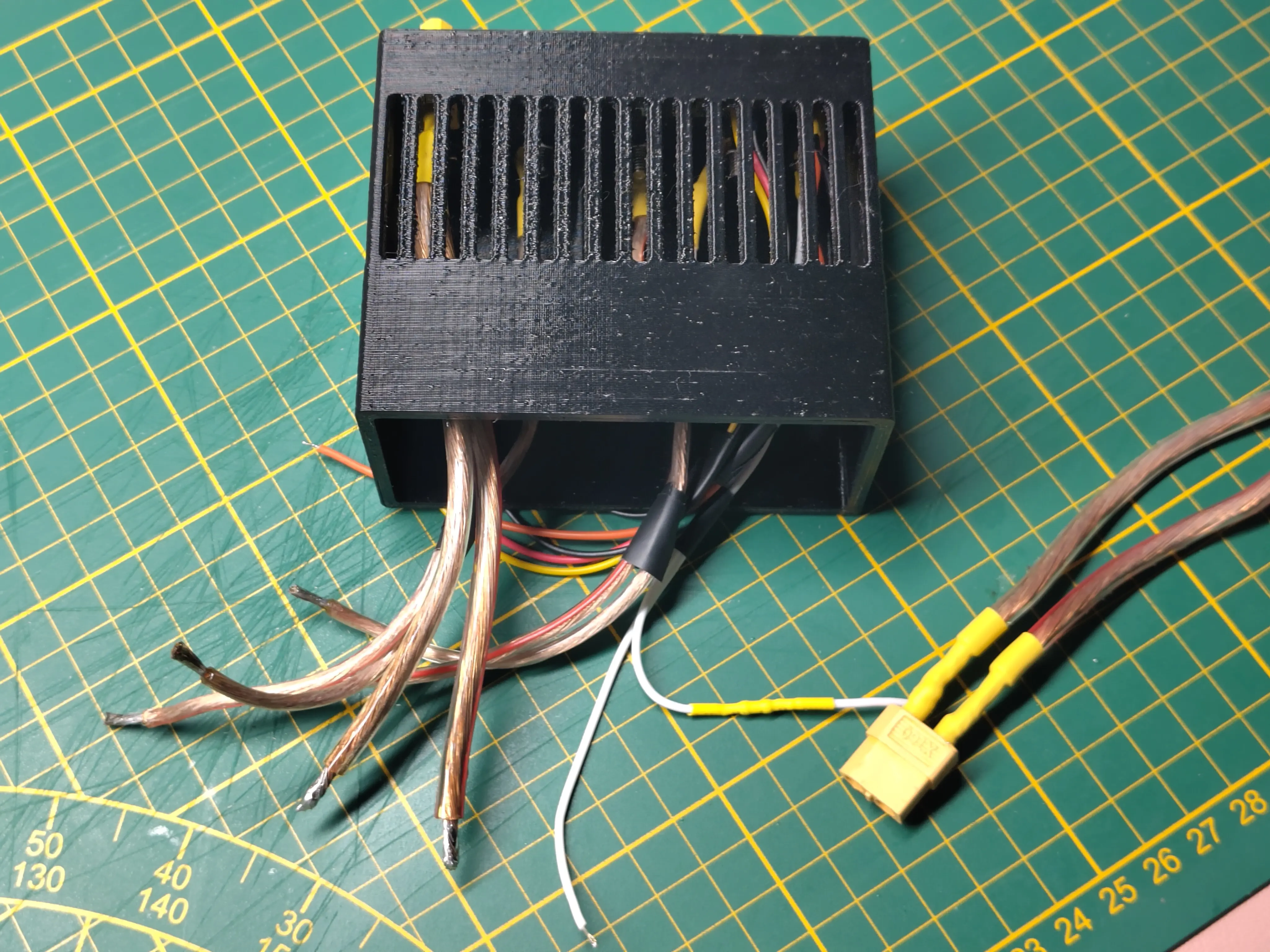
I’ve designed the enclosure to slide onto the PSU’s backside, right where it would mate with the server’s PSU socket. Since there’s only one bolt available to prevent the enclosure from sliding off of the PSU, I’ve designed the print to fit the unit with a relatively narrow clearance of 0.1mm. I’ve later made the fit even more snug with some painter’s tape, removing any remaining wiggle room from the equation.
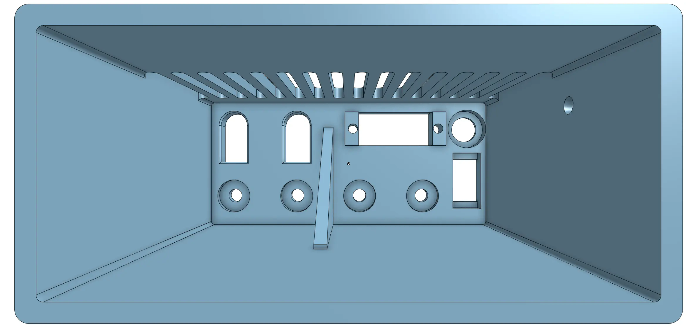
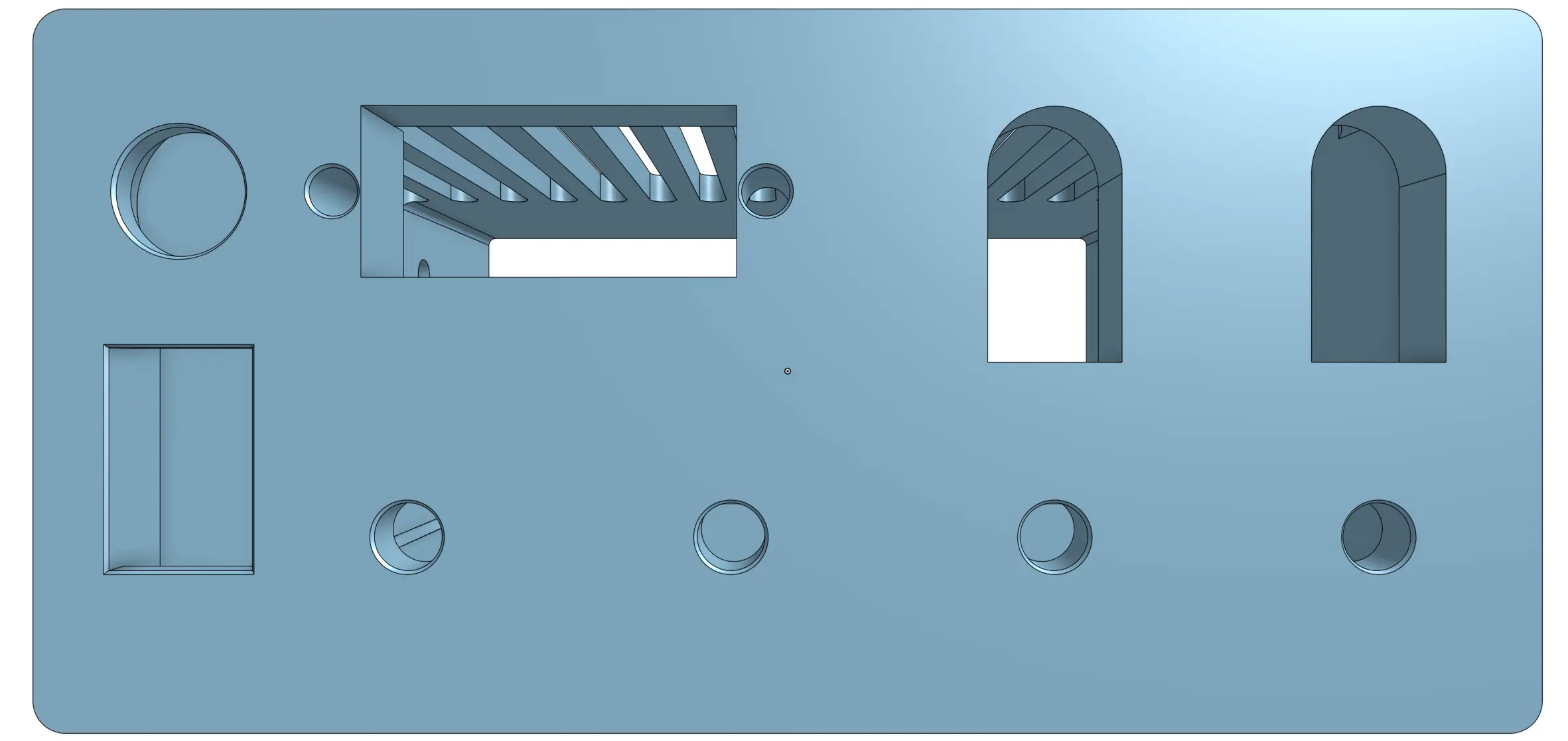
The front of the enclosure conveniently houses all of the necessary I/O, while the top-side facilitates cooling through air ducts. The spacing between the PCB and the frontplate allows for reasonably convenient maintenance access, with the obvious caveat being the longer cable runs. These become bunched up once the device is assembled, but it looks like there’s still some room left for appropriate ventilation. Stress tests will whether that’s true later on.
You can find the full Onshape CAD project over here.
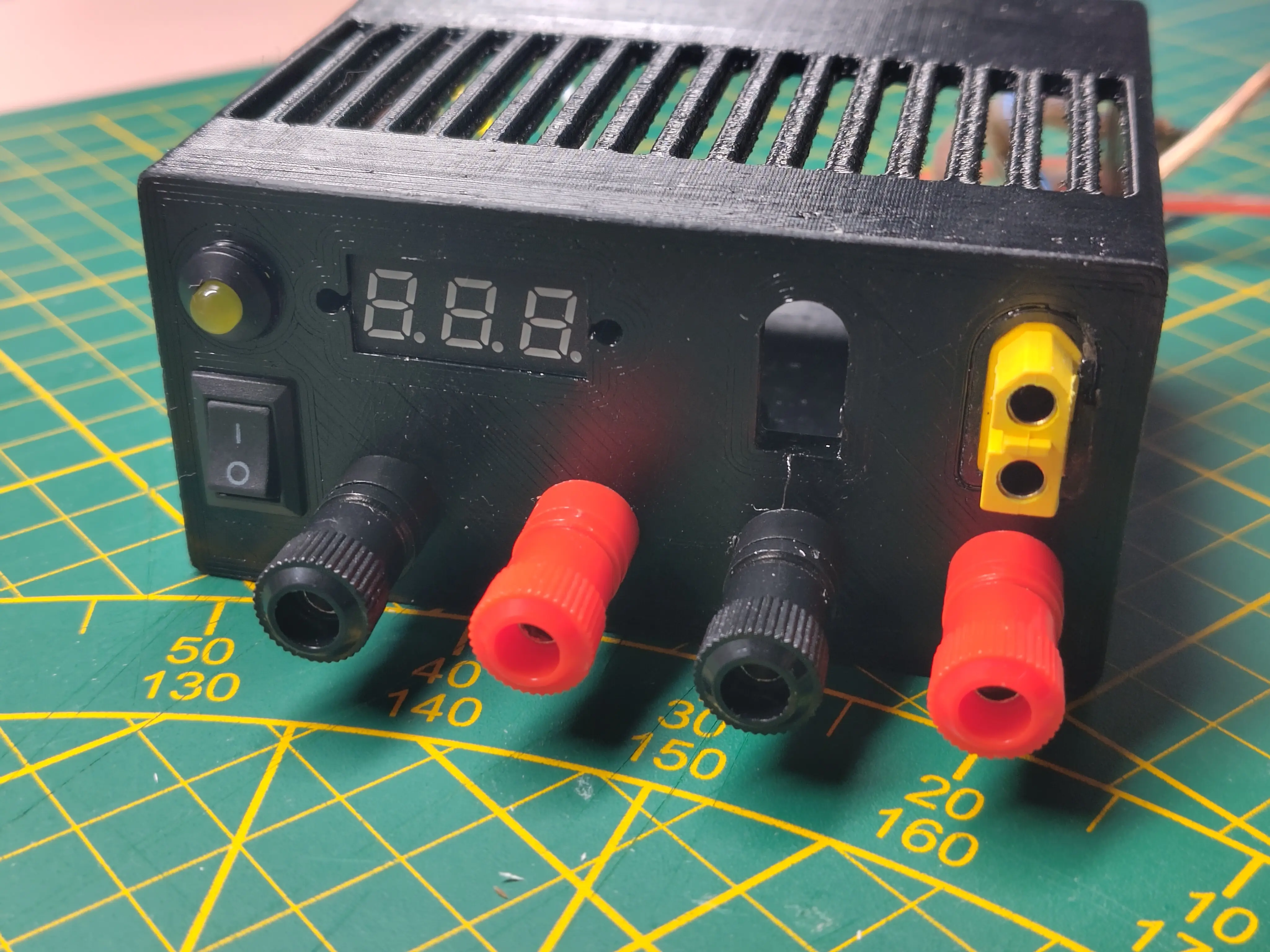
Assembly
With the enclosure printed, I’ve began soldering and assembling everything together. Here’s where I realized I could’ve (should’ve) separated the frontplate from the slide-on walls. That’s because positioning a M3 nut in place, while holding it from ~10cm away with nose pliers, is a royal pain in the ass. Alas, I’ve already printed the part and I didn’t want to waste the used resources.
If the frontplate was separate, I could assemble the front I/O comfortably, and then mate the frontplate to the enclosure walls with shape constraints and two or more bolts. Comfort of assembly is definitely something to keep in mind for future similar projects.
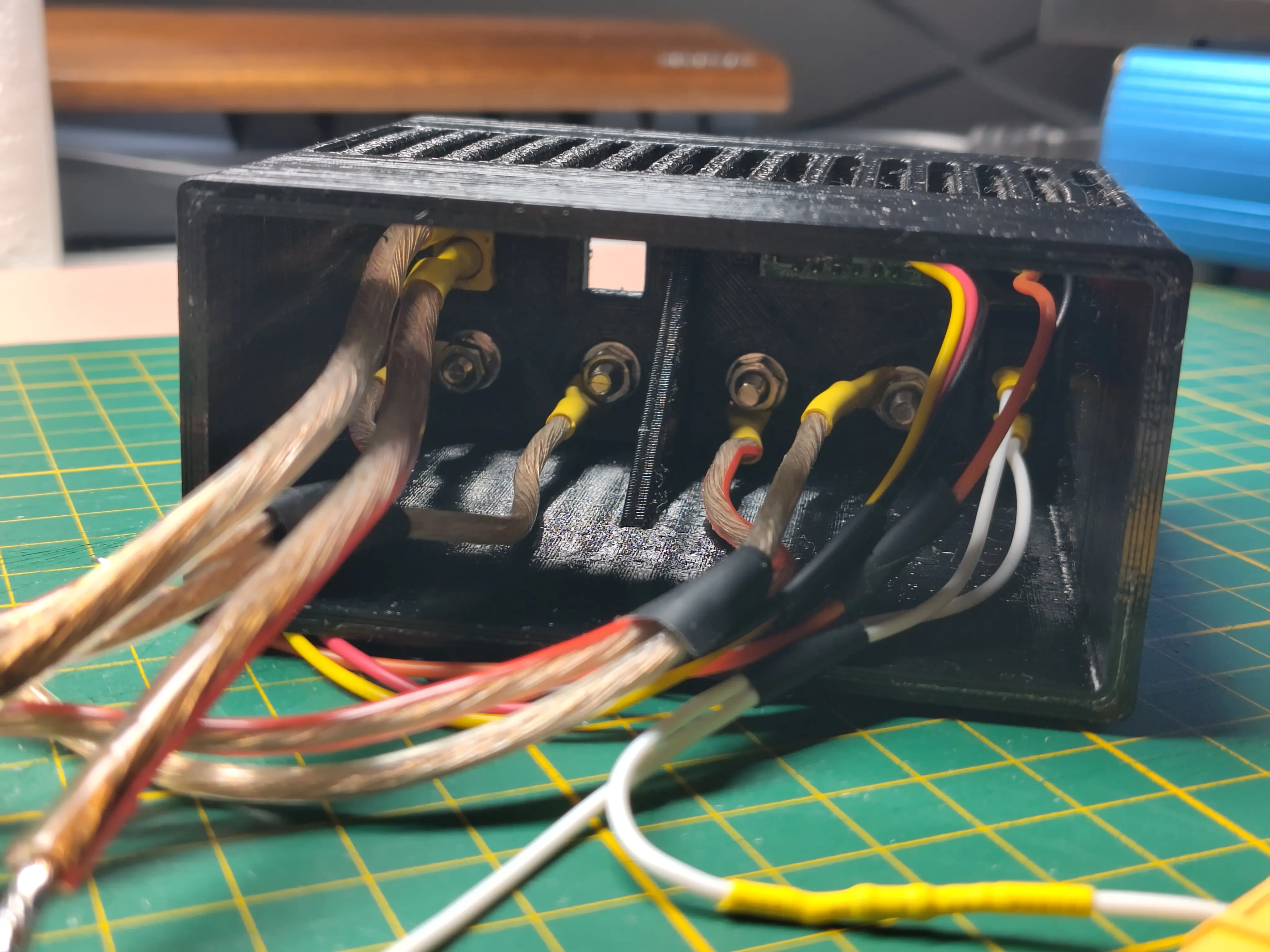
Soldering this was a challenge. The connectors were manageable, but anything on the PCB side was arduous, to say the least. I have a decently powerful soldering station (75W) with a large T12-KF tip, and it still was challenging to solder the power lines. The 12V copper traces are massive, they’re thick and cover a large area of the PCB. These characteristics result in a large thermal mass, acting like a heat sink. What worked for me is:
- Use lots of flux.
- Pre-heat the copper pad for 30+ seconds.
- Apply solder generously while continuously providing more heat.
- Dip the pre-soldered wire into the heated solder.
- Keep applying heat until the wire begins to wick the solder, meaning it has fused with the solder, hopefully creating a good electrical connection.
- Once cooled down, measure the resistance between the copper pad, and the far end of the wire. Seeing a low resistance is not a be-all check, but seeing a high resistance is definitely something to look into.
Testing
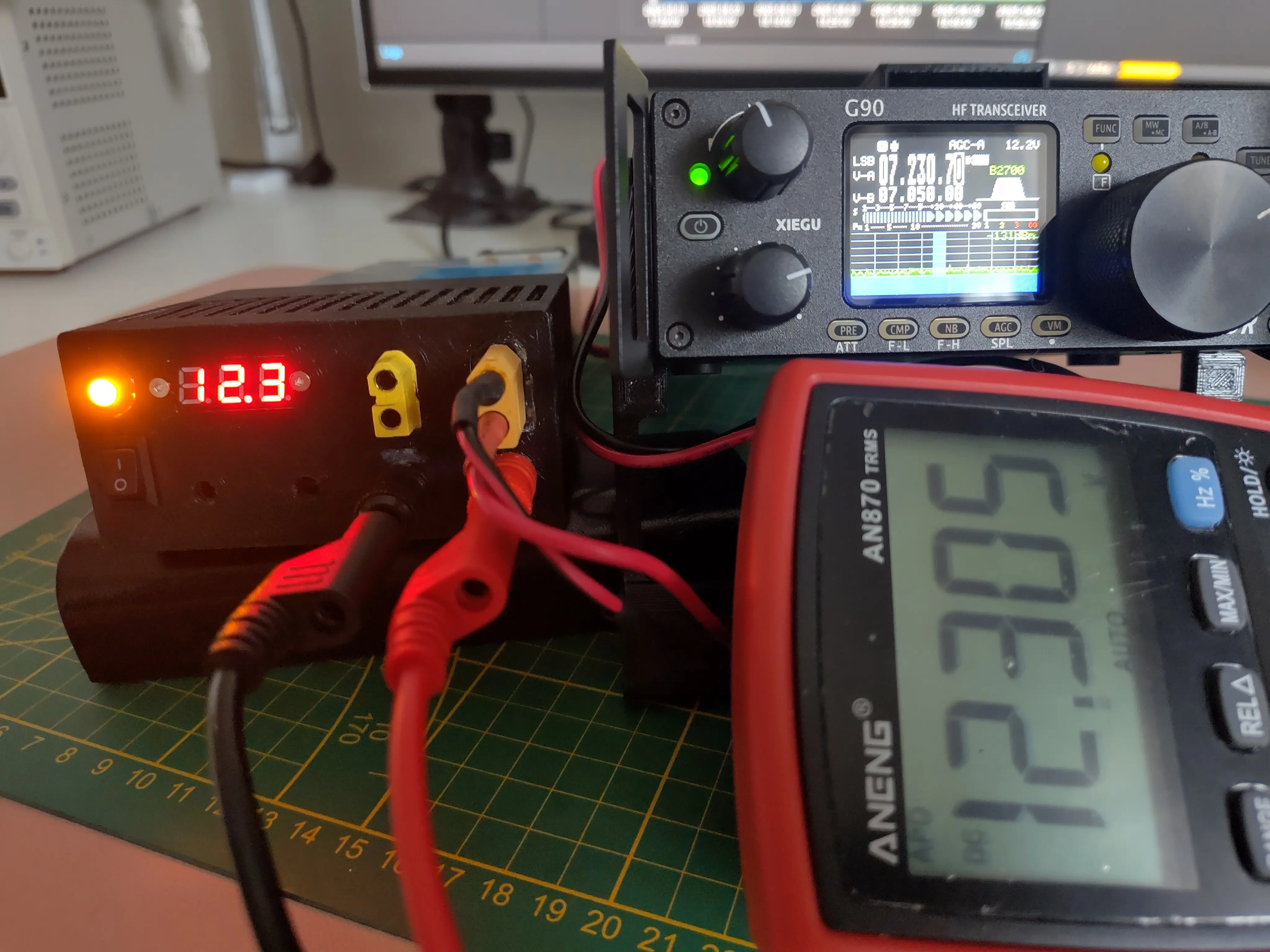
After confirming the output voltage was stable, I’ve connected the supply to my Xiegu G90 over one of the XT60 connectors. The radio powered up just fine, and that’s about as much as I could do until I get my ham license, since I don’t have a 50Ω dummy load to sink transmitter power into.
Possible Improvements
13,8V output voltage
Reportedly, there’s a way to modify the PSU to output a higher voltage, and tune the OVP (overvoltage protection) accordingly.
Since the Xiegu G90 exhibits roughly the same ERP on a supply of 12.8V, as on 14.4V (source – YO3HJV), I haven’t pursued any output voltage modifications for my unit. Technically there are some ERP differences across supply voltages, but they’re negligible and in my opinion not worth the hassle. Nevertheless, should you need a higher output voltage, here are some resources I found to get you started: